How does slewing work?
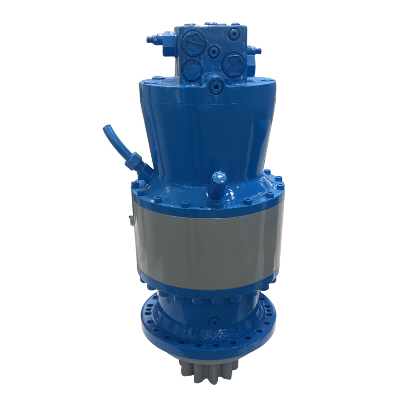
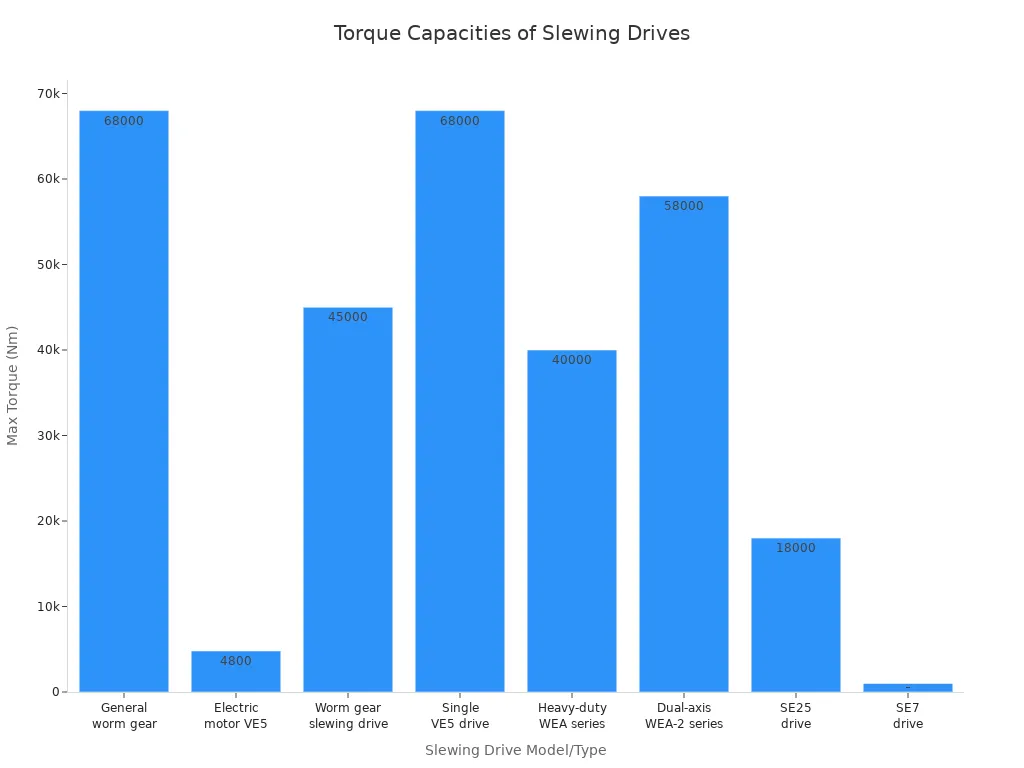
Slewing delivers rotational movement between machine components, supporting immense loads with precision. Heavy equipment, such as cranes and wind turbines, relies on advanced bearings and drives. The hydraulic slewing drive ensures reliable torque transfer. Typical load capacities span a wide range:
| Slewing Drive Model/Type | Torque Range (Nm) | Max Static Torque (kNm) | Applications |
|---|---|---|---|
| General worm gear slewing drives | 365 – 68,000 | Up to 190 | Cranes, wind turbines, solar trackers |
| Electric motor VE5 slewing drive | 4,800 | N/A | Worm gear transmission |
| Worm gear slewing drive | 2,500 – 45,000 | 190 | 360° swivel, high axial load |
| Single slewing drive VE5 | 500 – 68,000 | N/A | Solar tracking |
| Heavy-duty WEA series | 8,000 – 40,000 | N/A | Agricultural machinery |
| Dual-axis WEA-2 series | 16,200; 19,440; 48,000; 58,000 | N/A | Multi-directional, strong load-bearing |
| Worm gear slewing drive SE25 | 18,000 | N/A | Cranes, excavators |
| Worm gear slewing drive SE7 | 1,000 | N/A | High load, precision control |
Key Takeaways
- Slewing mechanisms enable smooth, precise rotation by using bearings and rolling elements that support heavy loads and reduce friction.
- Proper load distribution and torque control in slewing drives ensure stable and accurate movement, which is vital for heavy machinery like cranes and wind turbines.
- Regular maintenance, including timely lubrication and inspection, extends the life of slewing components and keeps equipment operating safely and efficiently.
Main Components of Slewing Mechanisms
Slewing Rings and Bearings
Slewing rings and bearings form the backbone of slewing mechanisms. These large, circular components support the entire weight of the rotating structure and enable smooth, controlled movement. The slewing ring typically consists of inner and outer rings, with rolling elements sandwiched between them. Bearings handle axial, radial, and moment loads, ensuring stability and reliable operation. The table below summarizes the main components and their functions:
| Component | Function |
|---|---|
| Slewing Ring | Supports heavy loads and enables smooth rotation. |
| Bearings | Manage axial, radial, and moment loads for stability. |
| Driving Mechanism | Provides torque for rotation, often via electric or hydraulic motors. |
Rolling Elements
Rolling elements, such as balls or rollers, reduce friction and wear inside the slewing ring. Their arrangement and type directly affect efficiency and durability. Four-point contact ball bearings distribute loads at four points, increasing adaptability. Cross roller bearings, with rollers set at right angles, offer superior load distribution and rigidity. Three-row roller bearings provide the highest load capacity, making them ideal for heavy-duty applications. The choice of rolling element impacts the mechanism’s performance and lifespan.
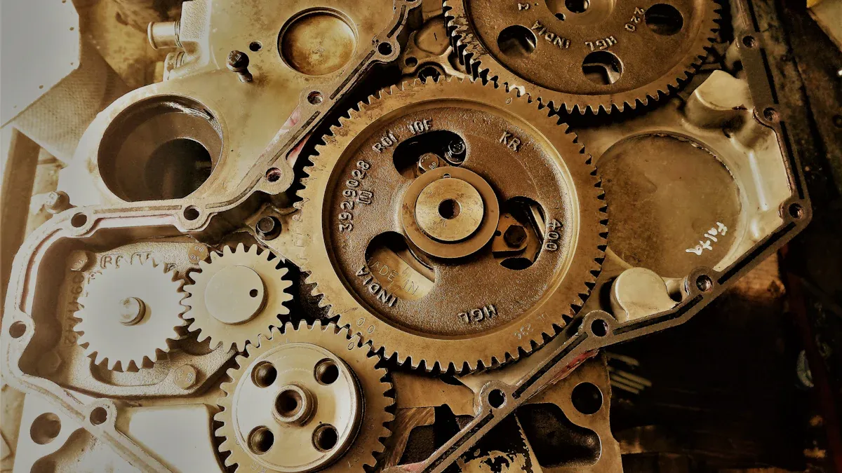
Gears and Drive Systems
Gears and drive systems transmit power from the motor to the slewing ring. Most slewing mechanisms use worm gear configurations, where a worm shaft drives a perpendicular gear. This setup reduces speed and increases torque, essential for heavy machinery. Modern designs often feature hourglass worm technology, which improves tooth engagement and durability. Dual-axis and dual-drive systems further enhance strength and control.
Seals and Lubrication
Seals and lubrication protect internal components and ensure long-term performance. High-quality seals prevent contaminants from entering the bearing. Proper lubrication reduces friction, prevents metal-to-metal contact, and dissipates heat. Regular maintenance and advanced lubrication technologies, such as solid lubrication, extend bearing life and reliability. Well-maintained lubrication systems also reduce noise and vibration, supporting smooth operation.
How Slewing Mechanisms Operate

Interaction of Components for Rotation
Slewing mechanisms achieve smooth rotation through the coordinated action of several key components. The process unfolds in a precise sequence:
- The slewing bearing sits between two main machine parts, such as a crane base and its rotating superstructure.
- External forces, including the weight of the equipment and operational loads, act on the bearing.
- Rolling elements—balls or rollers—move between the inner and outer rings of the bearing.
- These rolling elements distribute the applied load across their contact surfaces and the specially designed raceways.
- The raceways, with their optimized grooves, minimize stress and ensure even load sharing.
- Both the rolling elements and the raceway geometry resist deformation, even under heavy loads.
- This resistance allows for smooth, low-friction rotation between the connected components.
- The precise arrangement of rolling elements and the geometry of the raceways enable accurate motion control.
- As the machine rotates, the bearing continuously redistributes changing loads to maintain stability.
- Advanced materials and engineering practices extend the bearing’s service life and ensure reliable operation under diverse conditions.
Note: Wear and fatigue represent the most common failure modes in slewing bearings. These issues often arise from cyclic loads, friction, lubrication challenges, or improper assembly. Other potential problems include fracture, corrosion, and deformation. Regular inspection and maintenance help prevent these failures and ensure safe, reliable operation.
Load Distribution and Support
Slewing bearings must handle complex load scenarios during operation. These loads include:
- Axial loads: Forces acting perpendicular to the axis of rotation, often resulting from the weight of the equipment or external influences.
- Radial loads: Forces acting parallel to the axis, such as those caused by wind or centrifugal effects.
- Moment loads: Combinations of axial and radial forces, typically generated by the movement and weight of the machinery.
Load distribution across the bearing is rarely uniform. The curvature of the raceway and the number of rolling elements influence how loads spread across the bearing. Engineers optimize load distribution by adjusting the number and size of rolling elements, the contact angle, and the raceway profile.
Several engineering methods help maintain even load support:
- Proper lubrication reduces friction and wear, supporting uniform load distribution.
- Selecting the right grease—lithium-based, calcium-based, or polyurea-based—ensures optimal performance for specific operating conditions.
- Additives like molybdenum disulfide (MoS₂) enhance load-carrying capacity and anti-wear properties.
- Adhering to recommended lubrication intervals and quantities prevents premature wear and uneven stress.
- Four-point contact geometry allows a single row of balls to support axial, radial, and moment loads simultaneously.
- Internal clearance optimization accommodates misalignment and thermal expansion, maintaining rotational accuracy.
- Precision manufacturing, including CNC machining and induction hardening, produces high-quality raceways that withstand dynamic loads.
- High stiffness and compact design reduce system mass and support eccentric or offset loads effectively.
Tip: Simplified bearing designs with fewer parts not only ease assembly and maintenance but also contribute to consistent performance and even load distribution.
Torque Transmission and Control
Torque transmission lies at the heart of slewing mechanism performance. The slewing gear transfers torque from the machine’s power source—either an electric or hydraulic motor—to the rotating structure. This process enables horizontal rotation around a vertical axis, allowing precise positioning of heavy loads.
Key aspects of torque transmission and control include:
- The motor generates torque, which passes through a transmission system. This system may use pinions, worm gears, or other gear types.
- The slewing bearing receives the transmitted torque, supporting axial, radial, and moment loads while enabling controlled rotation.
- Worm gear transmissions offer a self-locking feature, which helps hold loads securely and allows for precise rotational control.
- The slewing drive assembly includes a housing and sealing system to protect internal components and maintain consistent performance.
- All components work together to provide accurate, smooth rotational movement and to keep the load stable during operation.
| Parameter | Value/Description |
|---|---|
| Slewing Drive Type | Spur gear slewing drive |
| Gear Ratio | 9:1 |
| Rated Output Torque | ~37 kN·m (standard heavy-duty model) |
| Rotation Center Diameter | 955 mm |
| Total Height with Adapter | 180 mm |
| Gear Backlash | ≤ 0.40 mm |
| Application | Heavy equipment with large tilting moments and heavy loads |
| Design Flexibility | Larger slewing drives available with diameters up to 2300 mm and higher torque |
Modern slewing mechanisms combine robust engineering, advanced materials, and precise manufacturing to deliver reliable torque transmission and control. This ensures that heavy machinery can operate safely and efficiently, even under demanding conditions.
Types and Practical Considerations
Hydraulic Slewing
Hydraulic Slewing systems use pressurized fluid to generate high torque and smooth, proportional control. These systems excel in heavy-duty applications, such as cranes and excavators, where continuous operation under significant loads is required. Hydraulic Slewing offers high mechanical efficiency and reliable performance in harsh environments. Operators benefit from precise movement at low speeds, which is essential for lifting and positioning heavy objects. Hydraulic Slewing systems require integration with hydraulic pumps and fluid management, making installation and maintenance more complex than electric alternatives. However, they deliver superior pulling power and can operate without overheating during extended use. The efficiency of Hydraulic Slewing improves further in hybrid systems, which reduce peak power and energy consumption.
Other Types of Slewing Mechanisms
Modern machinery uses several slewing mechanism types, each with unique features. Worm gear drives provide high gear reduction in a compact space and offer self-locking capability, which enhances safety. Spur gear drives use parallel shafts and straight teeth, making them suitable for simpler gear trains. Electric slewing mechanisms combine worm gears with slewing ring bearings, delivering precise, high-torque rotation and secure holding positions. The table below summarizes common slewing bearing types and their applications:
| Type of Slewing Bearing | Structural Characteristics | Typical Applications in Modern Machinery |
|---|---|---|
| Four-point Contact Ball Slewing Bearing | Simple structure, supports bidirectional axial and radial forces, some overturning moment capacity | Small cranes, material handling equipment |
| Double-row Different-diameter Ball | Two rows of balls, optimized load capacity and service life | Medium-sized port machinery, stacking cranes |
| Crossed Cylindrical Roller | High overturning moment and axial force capacity, high rotation precision | Large port cranes, bridge cranes |
| Three-row Cylindrical Roller | Large contact area, supports large axial, radial, and overturning moments | Ultra-large, heavy-duty port machinery |
Maintenance and Care
Proper maintenance ensures the longevity and reliability of slewing mechanisms. Operators should inspect bolts before each operation and after the first 100 working hours, then at 300 hours, and every 500 hours thereafter. Lubrication intervals range from every 200 to 500 hours, depending on load and environment. In harsh conditions, such as high humidity or dust, lubrication cycles should be shortened. Regular inspections help detect wear, damage, or contamination early. Cleaning, correct lubrication, and timely replacement of worn parts prevent excessive clearance, oil leakage, and overheating.
Common Applications
Slewing mechanisms play a vital role in many industries. Construction and industrial machinery rely on them for 360-degree rotation and heavy load support. Common applications include:
- Excavators and cranes for lifting and material handling
- Forestry machinery and forklifts
- Mining rigs and container trucks
- High-altitude vehicles and industrial robots
These mechanisms also appear in marine, renewable energy, aerospace, and automation sectors, supporting precise motion and stability.
Slewing mechanisms enable precise, heavy-duty rotation across industries, from cranes to wind turbines. Their advanced designs, such as three-row roller and cross roller bearings, support complex loads and ensure reliable performance. Regular maintenance, including Hydraulic Slewing systems, maximizes equipment lifespan and operational safety. Ongoing innovations continue to drive efficiency and precision.
FAQ
What is the main function of a slewing drive?
A slewing drive enables controlled rotational movement between two machine parts. It supports heavy loads and ensures precise positioning in industrial equipment.
How often should operators lubricate slewing bearings?
Operators should lubricate slewing bearings every 200 to 500 hours. Harsh environments may require more frequent lubrication to maintain optimal performance.
Can slewing mechanisms handle both axial and radial loads?
Yes. Slewing mechanisms support axial, radial, and moment loads. Their design distributes these forces efficiently, ensuring stability and long service life.