Unpacking Hydraulic Slewing Drives Core Components Explained
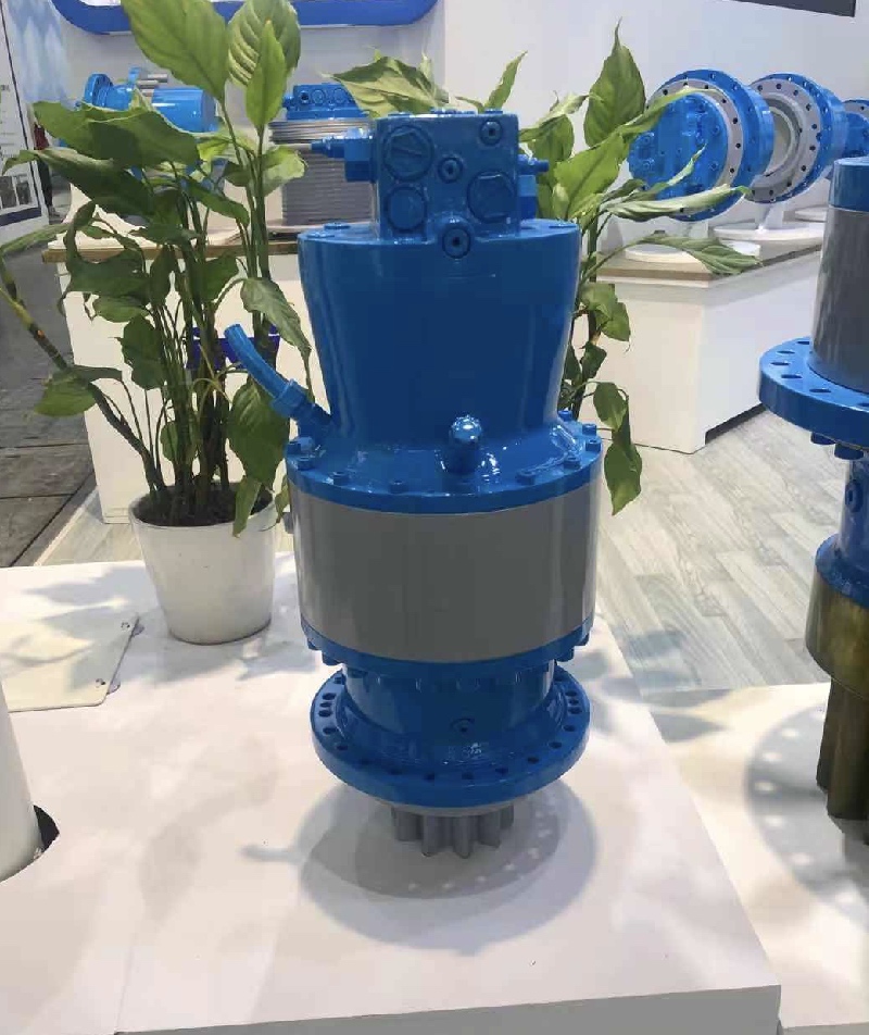
A hydraulic slewing drive is a compact, self-contained system. It provides powerful rotational motion for various heavy-duty applications. Engineers integrate these drives into machinery requiring precise and controlled turning capabilities. This technology combines hydraulic power with a gear reduction system. It enables significant torque output for the equipment.
Key Takeaways
- Hydraulic slewing drives turn heavy machines. They use fluid power to create strong turning force. This helps machines move big loads smoothly.
- These drives have key parts. A motor makes power, a gearbox makes it stronger, and a large bearing helps it spin. These parts work together for precise movement.
- Slewing drives are very strong. They can hold heavy things in place. They also work well in tough conditions.
Understanding Hydraulic Slewing Drives
What is a Hydraulic Slewing Drive?
A hydraulic slewing drive is a sophisticated mechanical system. It combines hydraulic power with a gear reduction mechanism. This device fundamentally consists of a hydraulic motor, a brake, a reducer, a valve group, and a gear end structure. Its modular design allows the hydraulic motor to transmit power to a gearbox. This transmission increases torque and reduces speed. It achieves the necessary low speed and high torque for various operations.
The system operates by generating power from a hydraulic motor. This power then transfers to a transmission system, such as a pinion or a worm gear, which creates torque. The generated torque applies to a slewing bearing. This entire process results in robust, smooth, and precise rotational movement of attached machinery. The motor provides the necessary power to operate the hydraulic slewing drive system. A worm gear, powered by the motor, converts the motor’s rotational motion into the desired movement for the platform. This worm gear engages with an outer ring gear connected to the slewing bearing. This ring comprises inner and outer rings linked by rolling elements. When the motor rotates the worm gear, it causes the outer ring gear to rotate relative to the inner slewing ring, enabling controlled rotational motion.
The Purpose of Hydraulic Slewing Drives
Hydraulic slewing drives fulfill critical functional requirements in heavy machinery. They handle axial, radial, and tilting loads. They also precisely control rotational movements. These drives deliver high torque at low speeds for managing heavy loads and precise rotational movements. They ensure smooth and efficient operations.
These drives offer significant mechanical advantages. They generate high torque and smooth, proportional control using pressurized fluid. They excel in heavy-duty applications requiring continuous operation under significant loads. They also offer high mechanical efficiency and reliable performance in harsh environments. Hydraulic slewing drives provide precise movement at low speeds, which is essential for lifting and positioning heavy objects. They deliver superior pulling power and can operate without overheating during extended use.
A key advantage is their inherent self-locking capability. This comes from the high friction angle of the worm gear setup. It allows the drive to hold heavy loads in a stationary position without a separate brake. This feature prevents back-driving, enhancing safety and reliability for applications where load stability is crucial. These drives generate immense output torque while operating at very low rotational speeds. This makes them ideal for moving heavy, slow-moving loads.
Their modular design simplifies installation and maintenance. High integration reduces the need to purchase and process individual parts. The system achieves low speed and high torque requirements by transmitting power through a gearbox. This improves labor productivity by streamlining the preparation process.
Many industries use hydraulic slewing drives. They are common in waste-water equipment, earth-moving equipment, and man-lifting platforms. Cranes, automation systems, road pavers, welding positioners, and turntables also utilize them. Typical applications include solar trackers and windmills. They are also found in aerial vehicles, photovoltaic power generators, wind power generators, and engineering machinery grapples. Hydraulic slewing gears are designed for use on hydraulic attachments for hydraulic excavators. They also appear in mobile and stationary handling machines. Specifically, hydraulic slewing devices are designed for excavator slewing solutions.
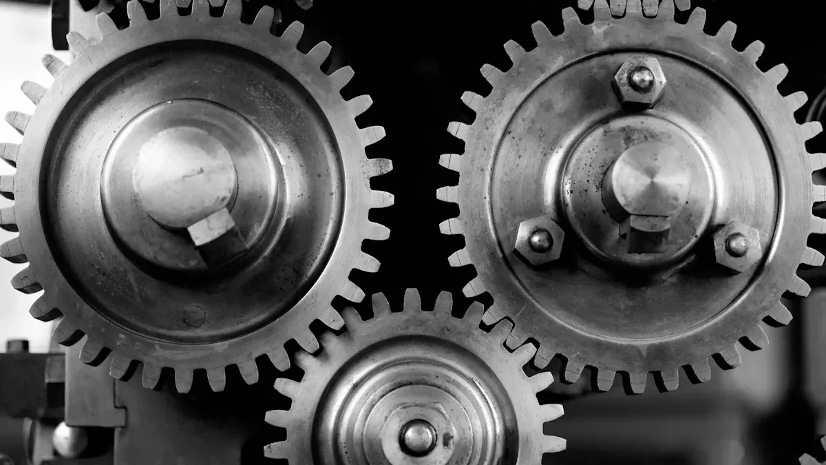
Core Components of Hydraulic Slewing Drives
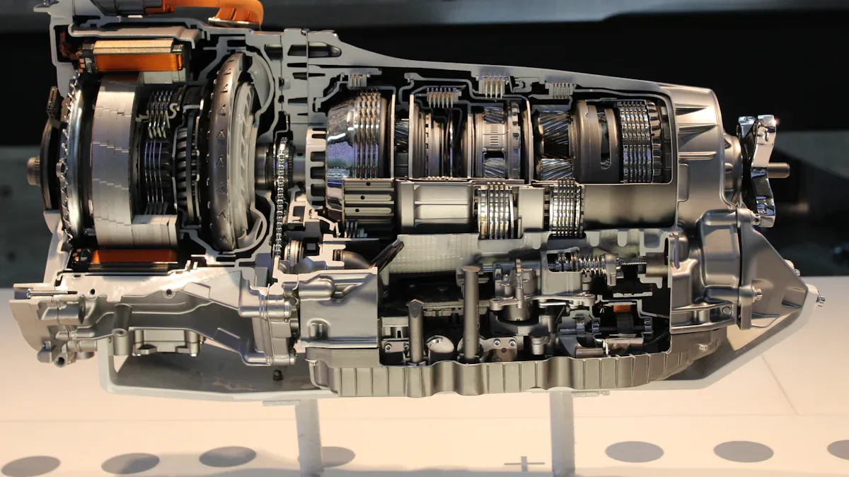
Hydraulic slewing drives are complex systems. They rely on several interconnected components. Each component plays a vital role in the drive’s overall function, efficiency, and reliability. Understanding these core parts helps in appreciating the drive’s robust performance.
Hydraulic Motor
The hydraulic motor serves as the power source for the slewing drive. It converts fluid power into mechanical rotational energy. This process begins when a hydraulic pump pressurizes fluid. The high-pressure fluid then enters the hydraulic motor. Inside the motor, components like gears, plungers, or hydraulic cylinders move relative to each other. This movement occurs as the high-pressure fluid flows through them. Internal pressure changes trigger this motion. Ultimately, this results in mechanical output in the form of powerful torque. The hydraulic system’s design allows precise control of output torque and speed. Adjusting the fluid flow and pressure achieves this control.
A hydraulic cycloidal motor, for example, is a positive-displacement rotary hydraulic motor. It converts hydraulic energy into mechanical rotational energy using cycloidal gearing. Its core mechanism involves a stationary stator with evenly spaced holes. A rotating rotor with pins engages these holes. An eccentric cam or disc, called a cycloidal drive, completes the setup. As hydraulic fluid enters the motor, it acts on the cycloidal drive. This action causes the drive to rotate. This rotation, in turn, moves the rotor within the stator. The engagement of the rotor’s pins with the stator’s pockets transforms the hydraulic energy into mechanical rotational energy. This design offers smooth power transfer and high torque at low speeds. The fluid’s pressure and flow rate determine the motor’s output torque and speed.
Planetary Gearbox
A planetary gearbox is an integral part of a hydraulic slewing drive system. It significantly multiplies the torque generated by the hydraulic motor. For instance, the IWHG44A model of a hydraulic slewing drive includes a hydraulic motor, a multi-stage planetary gearbox, a brake, and a valve block with braking capabilities. This configuration highlights the gearbox’s essential role in the system’s structure and operation.
Planetary slewing drives, developed from planetary gearbox technology, deliver high output torque. They range from 9 kNm to 400 kNm. They also possess a high peak bearing capacity. This implies the planetary gearbox’s specific function is to generate and transmit this significant torque within the slewing drive system. Planetary gearboxes are a type of ‘Hydraulic Component’ within ‘Slew Drives’. This suggests their role in the hydraulic functionality of these systems.
Planetary gearboxes offer several key advantages for torque multiplication:
- Exceptional Torque Transmission and Compact Size: The unique arrangement of a central sun gear surrounded by multiple planet gears allows superior torque transmission within a compact design.
- Improved Power Density and Durability: Load distribution among several planet gears, rather than a single gear, enhances power density and overall durability.
- High Gear Reduction Ratio: This enables precise speed control and significant torque multiplication. It is ideal for applications requiring accurate positioning, such as slewing drives.
- Exceptional Efficiency: Low friction losses and efficient power transmission minimize energy loss. This leads to a highly efficient transfer of power.
- High Torque Density: They deliver exceptional torque output relative to their size. This is crucial for handling heavy loads and challenging terrains effectively. It is especially important where compact yet powerful transmission is needed.
- Compact and Space-Efficient Design: They achieve a remarkably compact footprint due to their concentric gear arrangement. This is ideal for integration into space-limited applications while maintaining high power delivery.
- Even Load Distribution and Stability: They share loads across multiple planetary gears. This provides exceptional stability and reduces vibration. It is essential for precise positioning and consistent performance under varying loads.
- High Torque Density for Slew Drives in Renewable Energy: They provide high torque density for slew drives in wind turbine systems. This enables accurate positioning and rotation under variable wind loads. It enhances energy capture efficiency and system longevity.
Slew Bearing
Slewing bearings, also known as slew bearings, are large rotational rolling-element bearings. Engineers specifically design them to simultaneously support axial, radial, and moment loads. This design enables smooth rotational movement in heavy-duty machinery. They often operate under extreme stress. They accommodate both oscillating and continuous rotation.
Different types of slew bearings handle varying load capacities:
| Bearing Type | Load Handling Capabilities |
|---|---|
| Single-row ball slewing bearings | They withstand axial forces, radial forces, and tilting moments. |
| Double-row ball slewing bearings | They offer higher load capacity and rigidity. They suit applications with significant axial and radial loads. |
| Cross-roller slewing bearings | They handle very high axial, radial, and moment loads due to their crossed roller arrangement. |
| Three-row roller slewing bearings | They provide the highest load-carrying capacity. They are ideal for extremely heavy-duty applications with complex load combinations. |
| Ball-and-roller combination slewing bearings | They combine the benefits of both ball and roller elements. This optimizes performance under combined loads. |
Housing and Seals
The housing of hydraulic slewing drives is typically a cast part. This cast housing protects internal components from contamination, damage, and grease loss. This protection contributes to smoother operation and an extended lifespan for the drive. Seals within the housing prevent leaks of hydraulic fluid and ingress of external contaminants. They maintain the integrity of the internal environment.
Brake System
A brake system operates in conjunction with the hydraulic motor in a hydraulic slewing drive. It manages movement and maintains position when necessary. This combination ensures precise and reliable performance, even under significant loads. Many worm gear designs possess a self-locking characteristic. The specific angle of the worm prevents the load from causing the drive to rotate backward. This inherent property effectively functions as an intrinsic brake.
Common types of brake systems integrated into hydraulic slewing drives include:
- Hydraulic Thruster Brakes: Hydraulic cylinders or push rods activate these brakes. They press brake pads against a drum.
- Electro-Hydraulic Block Brakes: These systems combine electrical controls with hydraulic actuation. They achieve precise braking.
- Disc Brakes: Similar to automotive brakes, they use friction pads to press against a rotating disc. They offer excellent heat dissipation and smooth braking. They are a modern alternative often found in high-end equipment.
- Pneumatic Brakes: These brakes utilize compressed air for actuation. They are less common in tower cranes and more often seen in special machinery or industrial settings.
- Fail-Safe Brakes: Engineers design these to automatically engage during power loss or system failure. They frequently integrate with electromagnetic or hydraulic systems for enhanced safety.
Advanced braking systems provide smooth, controlled braking. They prevent damage to mechanical components. For example, the SOBO iQ controller manages braking torque based on speed and pressure feedback. It offers different braking profiles for various scenarios, including emergency stops and parking functions. It functions as a backstop, dynamic brake, and parking brake within the same system. This ensures controlled deceleration and secure holding of heavy loads. Benefits include controlled braking independent of load, adjustable brake ramps, compensation for variable friction, and real-time monitoring of the brake sequence. In tower crane slewing mechanisms, the slewing drive unit, comprising an electric motor, gearbox, and brake, is crucial. The brake’s role ensures precise stopping and secure holding of the rotating parts. This is essential for safe operation.
Electromagnetic brake coils provide controlled stopping and holding force. They generate a magnetic field when an electrical current applies. This engages a braking mechanism. Key selection factors for these coils include:
- Load Capacity/Torque Requirements: Underestimating this leads to brake failure, uncontrolled movement, equipment damage, and safety hazards.
- Voltage and Current Requirements: Mismatching these causes burnout, premature failure, or insufficient braking force.
- Response Time: A quick response is vital for safe stops, especially with high-speed loads or precise positioning needs. It prevents overruns or inaccuracies.
- Duty Cycle and Operating Environment: These factors influence the brake’s performance and longevity, especially with frequent or extended engagements.
How Hydraulic Slewing Drives Operate
Power Transmission in Hydraulic Slewing
Hydraulic slewing drives efficiently convert fluid power into mechanical rotational energy. Pressurized hydraulic fluid enters the motor chamber. This fluid exerts force on vanes or pistons within the motor. This force causes the rotor to spin, converting hydraulic energy into rotational motion. The drive utilizes a worm gear mechanism. An attached hydraulic motor provides input rotation to a worm. The worm engages with and drives a gear ring. This action results in the slow, powerful rotation of the entire bearing assembly. This configuration converts high-speed, low-torque motor input into low-speed, high-torque output, essential for moving heavy loads.
Achieving Rotational Movement
Hydraulic slewing drives achieve precise rotational movement through a sophisticated interplay of components. The hydraulic motor drives the pinion gear, which in turn rotates the large ring gear of the slewing platform. This direct drive allows for precise regulation of both rotational speed and direction. Gear mechanisms, such as worm or planetary gears, convert input motion into the desired rotational movement. This mechanism determines the gear ratio, directly influencing output torque and rotation speed. This enables precise control. The inherent design of the gear mechanism facilitates smooth, controlled, and precise movements, essential for accurate positioning. A dual-closed-hydraulic-circuit (DCHC) system achieves smooth acceleration and deceleration. It controls the displacement of the hydraulic axial piston pump via a programmed software algorithm and electronic control device. This system also enables controllable recuperation of kinetic energy during braking. This leads to smoother motion and more efficient operation.
Load Handling Capabilities of Hydraulic Slewing Drives
Hydraulic slewing drives demonstrate robust load handling capabilities due to specific design parameters. A higher gear safety factor directly enables the gear to withstand larger loads without bending or fracture. This is critical for heavy-duty machinery. A higher safety factor also links to superior material quality and robust manufacturing processes. This results in enhanced wear resistance of the gear tooth surfaces. Furthermore, a higher safety factor improves the gear’s ability to absorb and withstand sudden impact loads or vibrations. These can arise from uneven terrain, abrupt stops, or external collisions.
Hydraulic slewing drives provide powerful, precise rotation. Understanding their components ensures reliability. The future embraces electrification and intelligent control, making systems smarter for automation. It also prioritizes energy-regenerative systems and advanced gear technologies, like double-enveloping worm gears, for enhanced efficiency and power density.
FAQ
What is the primary function of a hydraulic slewing drive?
A hydraulic slewing drive provides powerful, controlled rotational motion for heavy machinery. It converts hydraulic power into mechanical torque, enabling precise turning and positioning of loads.
How does a planetary gearbox contribute to a slewing drive’s performance?
A planetary gearbox significantly multiplies the hydraulic motor’s torque. It delivers high output torque within a compact design, ensuring efficient power transmission and precise speed control for heavy loads.
Why are slew bearings crucial for heavy machinery?
Slew bearings support axial, radial, and moment loads simultaneously. They enable smooth, stable rotational movement. This design ensures the machinery can handle diverse forces during operation.