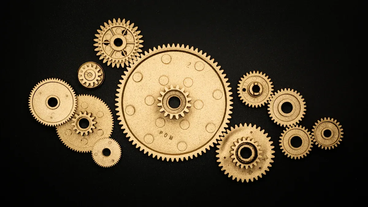
What is a spur and pinion gear?

A spur gear features straight teeth and rotates on a parallel axis. A pinion gear, usually the smaller gear in a pair, meshes with the spur gear to transmit motion. Together, spur and pinion gears efficiently transfer power in many industries, including automotive, aerospace, and Hydraulic Slewing applications.

Key Takeaways
- Spur and pinion gears work together to transfer power efficiently between parallel shafts, with the pinion usually being the smaller driving gear.
- These gears offer very high efficiency, often above 98%, making them ideal for machines that need reliable and precise motion control.
- Spur and pinion gears are widely used in many industries, including automotive, aerospace, and hydraulic slewing, due to their durability and ease of maintenance.
How Spur and Pinion Gears Work
Basic Mechanics
Spur and pinion gears operate on simple yet precise mechanical principles. These gears transmit rotary motion between parallel shafts, maintaining a constant velocity ratio. The involute tooth profile, a curved shape, ensures smooth meshing and steady speed during operation.
- The pitch circle is an imaginary circle that passes through the point where the teeth of two gears engage. This point, called the pitch point, is where the gears transfer motion most efficiently.
- Conjugate action means that as one gear tooth pushes another, the driven tooth moves in perfect proportion, keeping the speed ratio fixed.
- The gear ratio depends on the number of teeth or the diameter of the pitch circles. A larger gear paired with a smaller pinion increases torque but reduces speed.
- Key terms include:
- Module (metric measure of tooth size)
- Diametral pitch (imperial measure)
- Pressure angle (usually 20°)
- Contact ratio (average number of teeth in contact)
Note: The contact ratio helps share the load between teeth, making the gear system stronger and smoother.
Material selection plays a crucial role in gear performance. Steel, bronze, and thermoplastics like nylon or acetal are common choices. Steel offers strength and durability, while plastics reduce noise and resist corrosion. Bronze and stainless steel perform well in wet or harsh environments. Engineers often use heat treatments such as carburizing or induction hardening to increase surface hardness and extend gear life.
A typical spur and pinion gear set uses the pinion as the driving gear. Its teeth mesh with those of the spur gear, transferring motion and torque. The straight teeth of spur gears allow for efficient power transfer between parallel shafts.
Motion and Power Transfer
The interaction between spur and pinion gear teeth is precise and efficient. The teeth mesh at their pitch circles, where the transfer of rotational motion and torque occurs. As the pinion rotates, its teeth push against the spur gear’s teeth, causing the spur gear to turn. The contact point moves along the line of action, an imaginary line that guides the force transmission between gears.
- The gear teeth engage at the pitch circle, transferring motion and torque.
- The contact point travels along the line of action, ensuring smooth force transfer.
- Involute tooth profiles minimize impact loads and allow for steady engagement.
- Geometric factors like pitch circle diameter, pressure angle, and backlash influence how smoothly the gears mesh.
- Backlash, a small gap between teeth, prevents jamming and allows for thermal expansion.
- The meshing angle affects friction and noise during operation.
- These features enable the pinion to drive the spur gear with high efficiency and reliability.
The gear ratio, defined as the number of teeth on the driven gear divided by the number on the driving gear, directly affects speed and torque. For example, a 2:1 gear ratio means the driven gear turns at half the speed of the pinion but delivers twice the torque. This relationship allows engineers to design gear systems that match specific performance needs.
| Gear Type | Efficiency Range | Key Points on Efficiency and Losses |
|---|---|---|
| Spur Gears | 98-99% | Very high efficiency; minimal losses mainly from tooth friction and lubrication churning |
| Helical Gears | 98-99% | Slightly lower than spur due to axial thrust and sliding action |
| Double Helical | 98-99% | Comparable to spur and helical gears |
| Bevel Gears | 98-99% | High efficiency but lower than spur due to sliding action |
| Worm Gears | 20-98% | Significantly lower efficiency, highly dependent on gear ratio and conditions |
| Crossed Helical | 70-98% | Lower efficiency due to sliding and complex tooth engagement |
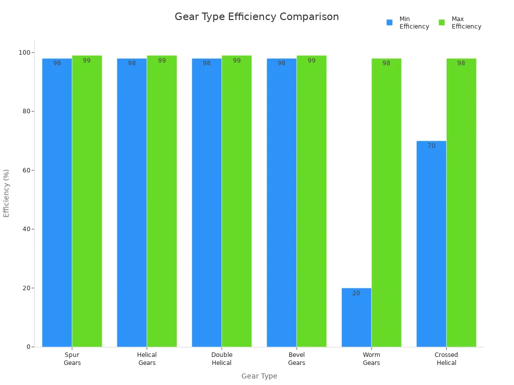
Spur and pinion gears stand out for their high efficiency, typically reaching 98-99%. This makes them ideal for applications where minimal energy loss is critical. However, spur gears tend to produce more noise than helical gears because their teeth engage suddenly, releasing energy abruptly and causing vibration. Helical gears, with their angled teeth, operate more quietly but are more complex to manufacture.
Maintenance is essential for reliable gear operation. Common issues include wear, misalignment, and insufficient lubrication. Regular inspection and proper lubrication help prevent problems such as pitting, spalling, and abrasive wear. Choosing the right materials and maintaining correct alignment extend the lifespan of spur and pinion gears, ensuring smooth and efficient power transfer in a wide range of machines.
Key Features and Differences
Spur Gear Design
Spur gears stand out for their straight teeth, which run parallel to the gear axis. This design allows for direct contact between tooth surfaces, resulting in high efficiency—often above 98%. Spur gears transmit rotary motion between parallel shafts and have a simple cylindrical shape. Most spur gears are external, with teeth on the outside edge, causing the driven gear to rotate in the opposite direction. Internal spur gears, with teeth on the inside, allow for closer shaft spacing and higher torque but require more complex manufacturing.
| Feature | Spur Gears | Other Gear Types (Summary) |
|---|---|---|
| Tooth Design | Straight teeth parallel to gear axis | Helical: angled teeth; Bevel: conical; Worm: screw-like; Planetary: multiple planet gears |
| Shaft Orientation | Parallel shafts | Helical: parallel; Bevel: intersecting; Worm: non-parallel; Planetary: parallel/coaxial |
| Efficiency | High (98% or more) | Helical: slightly lower; Bevel: moderate; Worm: lower; Planetary: high |
| Noise Level | Noisy at high speeds | Helical: quieter; Bevel: moderate; Worm: quiet; Planetary: moderate |
| Complexity & Cost | Simple, low cost | Helical: more complex; Bevel: moderate; Worm: complex; Planetary: highly complex |
The number of teeth on a spur gear affects gear ratio, smoothness, and load distribution. Engineers often select at least 18 teeth for standard designs to avoid undercutting and ensure reliable operation.
Pinion Gear Characteristics
Pinion gears are usually the smaller gear in a pair. Their position in a gear train determines the system’s mechanical advantage and force output. When used in rack-and-pinion systems, the pinion’s torque and speed directly influence the force and movement of the rack. In planetary gear trains, flexible mounting of pinion gears helps distribute loads evenly, improving durability and reducing stress. Advances in materials, such as carbon fiber-reinforced polymers, have increased pinion gear durability, allowing them to perform well even under challenging conditions.
Tip: Selecting the right material and tooth count for a pinion gear can extend its lifespan and improve system performance.
Spur Gear vs. Pinion Gear
Spur gears and pinion gears share similar manufacturing processes, both benefiting from simple and cost-effective production. Spur gears serve as the main driver or driven gear, while pinion gears often act as the input or output, especially in rack-and-pinion or planetary systems. Spur gears typically handle rotary power transmission, whereas pinion gears can convert rotary motion to linear movement. Both types now use sustainable manufacturing methods, such as near-net shape forging and recyclable materials, to reduce environmental impact. Their differences in size, function, and application make each essential in mechanical systems.
Practical Applications and Hydraulic Slewing
Everyday Uses and Examples
Spur and pinion gears appear in many daily products and industrial machines. People find these gears in car transmissions, steering systems, and even bicycles. In homes, washing machines, blenders, and clocks rely on spur gears for smooth operation. Pinion gears play a key role in rack and pinion steering, helping drivers control vehicles with precision. Factories use these gears in conveyor belts, pumps, and packaging machines to move products efficiently.
| Industry / Machinery Type | Practical Applications of Spur and Pinion Gears |
|---|---|
| Automotive | Gear reduction, steering systems, road rollers |
| Industrial Machinery | Gearboxes, conveyors, pumps, compressors, machine tools |
| Aerospace | Flight controls, plane engines, landing gear |
| Power Generation | Wind turbines, hydroelectric stations |
| Textile Industry | Spinning, weaving, dyeing machinery |
| Consumer Products | Clocks, printers, power tools |
| Household Appliances | Washing machines, blenders, dryers |
| Robotics and Automation | CNC machines, servo mechanisms |
| Low-Speed Vehicles & Equipment | Bicycles, kilns, ball mills |
| Mechanical Actuators | Rack and pinion systems |
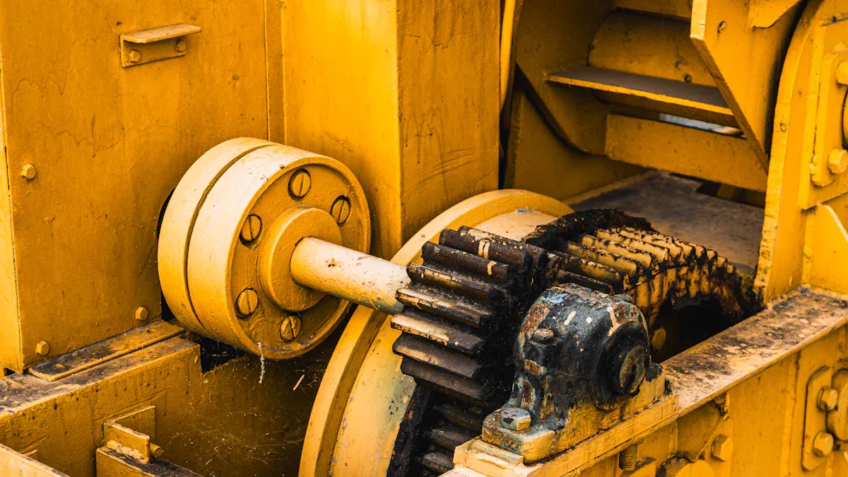
Hydraulic Slewing systems use spur and pinion gears to rotate heavy equipment like cranes and excavators. These systems convert hydraulic motor power into controlled movement, making it easy to lift and turn large loads. The compact design of Hydraulic Slewing drives allows for plug-and-play installation, saving time during assembly.
Importance in Machines and Equipment
Spur and pinion gears support the core functions of many machines. They provide high efficiency, often reaching up to 98%, which reduces energy loss and keeps equipment running smoothly. In Hydraulic Slewing applications, these gears ensure precise rotation and stable torque, even under heavy loads. The sealed housing of Hydraulic Slewing drives protects gears from dust and water, making them reliable in harsh environments.
Manufacturers choose spur and pinion gears for their durability and easy maintenance. Hydraulic Slewing drives often use strong materials like steel or stainless steel to handle tough jobs. These drives can work with one or two hydraulic motors, offering flexibility for different machines. Engineers value Hydraulic Slewing for its ability to deliver fast acceleration and high torque in a compact space.
The global market for machines using spur and pinion gears is large. In 2024, over 15 million spur gear units were sold, with the automotive sector as a major user. Hydraulic Slewing technology continues to grow in importance as industries demand more efficient and reliable equipment.
Spur gears feature straight teeth and transfer power between parallel shafts. The pinion, always the smaller gear, meshes with the spur gear to control speed and torque.
- Spur and pinion gears deliver high efficiency, reliability, and precision in machines like gearboxes, robotics, and vehicles.
- Engineers expect continued innovation with lightweight materials and advanced manufacturing, ensuring these gears remain vital in future technology.
FAQ
What is the main difference between a spur gear and a pinion gear?
A spur gear can be any size, while a pinion gear is always the smaller gear in the pair. The pinion usually drives the spur gear.
Why do engineers choose spur and pinion gears for machines?
Engineers select spur and pinion gears for their high efficiency, simple design, and reliable power transfer. These gears work well in many machines and require minimal maintenance.
Can spur and pinion gears handle heavy loads?
Yes. Spur and pinion gears, especially those made from strong materials like steel, can handle heavy loads in equipment such as cranes, excavators, and industrial gearboxes.